FLEX-E-TEST
Project Leader: Oleksandr Glushko and Megan Cordill
1. General information
FLEX-E-TEST is a new technique for mechanical (bending) testing of functional films on flexible substrates which was developed in Erich Schmid Institute for Materials Science (Leoben, Austia) during the FFG Sondierung project No.843648 in partnership with NanoTecCenter Weiz (Weiz, Austria). With this technique virtually any flexible thin film structure can be subjected to a controlled number of bending-unbending cycles with pre-defined speed, bending radius and bending direction.
2. Working principle of the FLEX-E-TEST
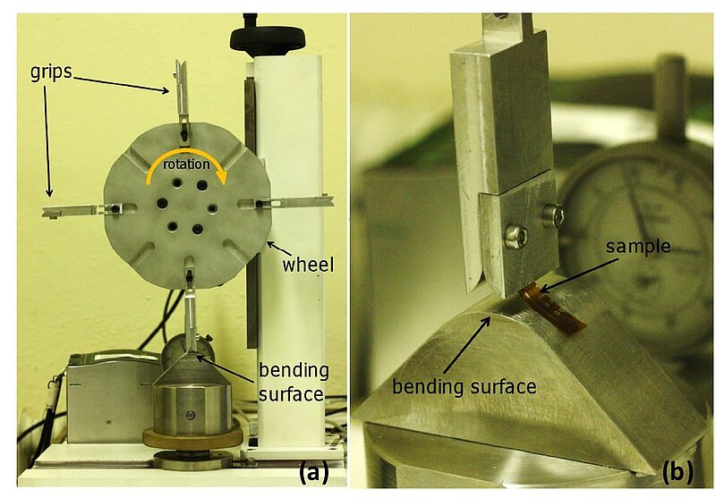
FLEX-E-TEST testing device consists of (Fig. 1):
- computer-controlled motor
- test wheel attached to the motor
- grips with quarter-circle-shaped ends
- bending surface
The main part of the FLEX-E-TEST device is the testing wheel with eight slots for sample holders/grips with curved ends. The sample is fixed between the grips with the help of two screws (Fig. 1b). The curvature of the grips defines the bending radius which will be applied during the test. The distance between the ends of the grips and bending surface should be adjusted by vertical movement of the wheel to assure that samples are fully bent over the curved grips ends during wheel rotation. Then an appropriate rotation program defining rotation speed, rotation direction, and number of cycles is defined. By means of the motor controller software the rotation direction and rotation speed can be changed during a single test. As soon as the samples are mounted, vertical wheel position is set, and the rotation parameters are chosen the test can be started. During operation the wheel rotates bringing the samples sequentially in contact with the bending surface which causes bending to a radius defined by the curvature of the grips.
3. First testing results
FLEX-E-TEST technique was applied to several different sample types on flexible substrates. One of the first goals was to investigate the influence of loading conditions on the mechanical failure due to repeated bending. Three different loading conditions are defined as following:
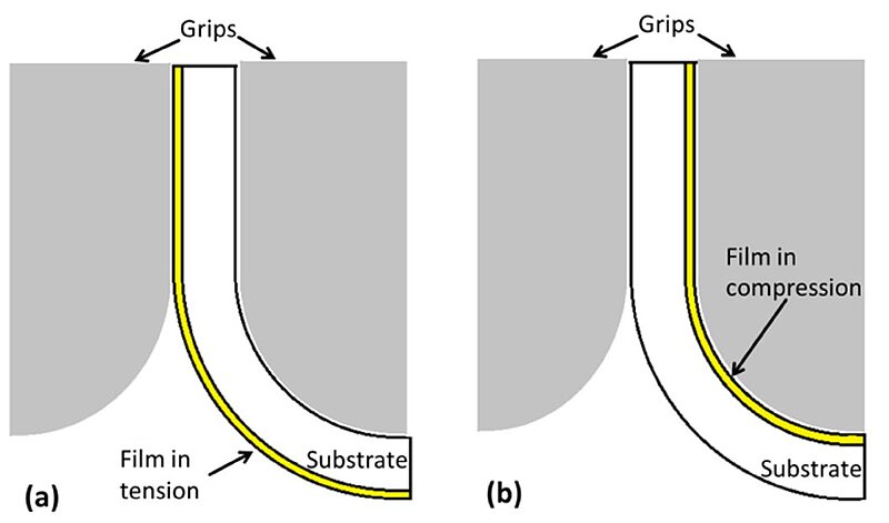
a) “tensile bending” means repeated bending when the film/structure is on the outersurface of the substrate during bending (Fig. 2a). Corresponds to application of cyclic tensile strain
b) “compressive bending” means repeated bending when the film/structure is on the inner surface of the substrate during bending (Fig. 2b). Corresponds to application of cyclic compressive strain.
c) “tensile-compressive bending” means that rotation direction is changing after each 10 cycles which results in repeating blocks of 10 cycles of tensile strain and 10 cycles of compressive strain.
These three different loading conditions were applied to ink-jet printed silver lines with thickness of 700 nm and width of 500 µm on 130 µm thick PEN substrate. The bending radius was 5 mm which corresponds to the strain of 1.3%. The cycle number changes between 1000 and 50000.
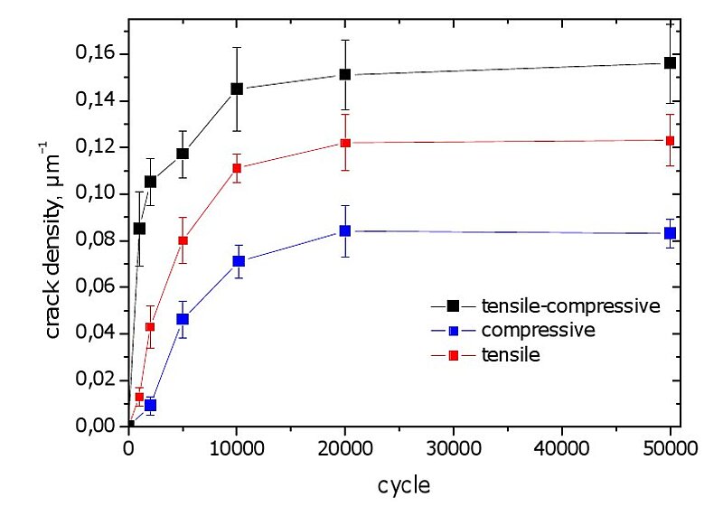
Application of bending cycles induces cracking of printed silver lines. Typical SEM micrograph of the cracks is shown in Fig. 3. In order to characterize the development of bending fatigue damage the linear crack density, i.e. average number of cracks per unit length, was evaluated for different cycle numbers. The result of this evaluation is shown in Fig. 4 for three loading conditions. Qualitatively the evolution of crack density is similar for all three loading conditions: increase up to approximately 10000 cycles and saturation for higher cycle numbers. What is however interesting is the difference in saturation values of crack density which is around 0.15 cracks/µm for tensile-compressive loading, 0.12 cracks/µm for tensile bending and 0.08 cracks/µm for compressive bending. Thus, although the bending radius and consequently the strain was the same in all cases, tensile-compressive loading induces almost two times more cracks then compressive loading.

4. Advantages of FLEX-E-TEST
FLEX-E-TEST technique is a new method which is designed for flexible electronics applications and provides several important advantages in comaprison to other bending tests reported in the literature:
1. The technique is fast due to the ability to test up to 8 samples at the same time. This is especially important if different fabrication parameters (ink type, layer thickness, curing parameters, adhesion promoters, etc.) and thus many different samples should be evaluated with respect to mechanical stability.
2. Possibilty to bend samples automatically in both directions is an important advantage which is not provided by other tests like “collapsing radius test”.
3. Clearly and strictly defined bending radius. No need to make recalculations.
4. There is virtually no restriction of sample form-factor. FLEX-E-TEST can be easily adapted to test large samples with specific shape.
5. Large variety of bending radii can be realized, from close to infinity to 1-2 mm.
6. FLEX-E-TEST allows to simulate conditions which are very close to “real” bending when a device is bend, unbend, and the next bending occurs after some time delay. The method can be also easily adapted to work with flexible electronics for bioapplications, e.g. “epidermal electronics”. Generally, almost all parts of the FLEX-E-TEST device are replaceable and adjustable granting a large versatility of possible application.
Acknowledgements
FFG